Saturday, March 29, 2014

More LED Matrix shenanigans!

It's been about two weeks since my last post.   It took a few nights to wire the sparkfun button pads, and a few more days for various parts, but "we have lift-off"!!   The wiring really got stupid, fortunately I had a ton of leftover cuttoff wire from 3d printers! I used some protoboard which connects to the button pads via header / connector, then i wired up R/G/B/Row/Button connectors.   This literally took me 3 sessions of 2-3 hours each.    be patient, tin EVERY wire and double check each joint!


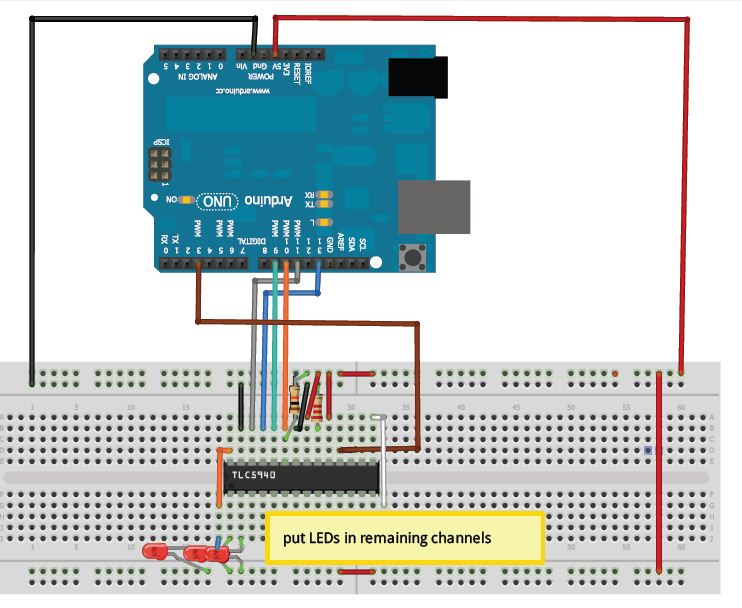
After wiring it all up, I realized I didn't have anything to connect this to my breadboard!  So i ordered some pre-wired 8 pin connectors, and after a few hours of tinkering (mostly trying different wiring schemes mentioned in the code), I had a few blinky lights!


I'd originally encountered the "Demystifying the TLC5940" ebook and code which got me pretty close, but my row scanning setup was slightly different.   A little more googling lead me to nearly exactly what i needed!
https://github.com/jblang/tlc5940demystified

This guy is using a similar shift register setup to select rows.   He's using a shift register / transistor in one combo device.   I'm using 74HC164 which allows you to shift out w/out the use of a latch pin, and that powers TLC59213 to source the current for the LED's.     I ran the clock of the 164 to the clock of the 59213, adjusted some pins in the code and got what you see above!

Now, this is certainly progress, but its not entirely correct. First off, he's only using a Red/Green matrix, I need one more color!   From what I can tell, in his wiring, he's doing R-G-R-G, etc.   He's also only using 1 TLC5940.  On mine, I'm doing 1-TLC5940 for each color - RRRRRRRRRRRRRRRGGGGGGGGGGGGGGGBBBBBBBBBBBBBB..   I found getting this sorted was just a matter of changing some of the math that selects the pins.   A few more quick changes, and I had both his Plasma and Scoll functions working well!

I've made a fork of the above project on GitHub which can be found here:
https://github.com/billieblaze/tlc5940demystified

Next, I'll be adding some of the Adafruit GFX library functionality and integrating my button row scanning!

Friday, March 14, 2014

Spectrum Analyzer with Arduino + Adafruit 16x32 RGB Matrix!

As you may have noticed, I've been toying around with tons of LED's and looking at ways they apply to the user interface of music machines.   One of the first use cases I had for an LED matrix was a spectrum analyzer!    Obviously, this is nothing new and the ground work has totally been laid out by a bunch of people smarter then I, but its interesting none-the-less.

I came across three projects I found interesting

1)  32 x 16 led matrix arduino spectrum analyzer


Pretty cool, but no source available..  looks like a pretty solid refresh rate though.   Some detail about its workings in the comments

2) Arduino / Processing Audio Spectrum Analyzer


This one has source code (yay).  It uses processing on the pc to do the FFT.    This is the basic configuration I've got setup in my first video which is my implementation.     On mine, I'm just capturing off the mic on my laptop, but you can target pretty much any output.   I'd like it to be sort of a stand alone audio device, which leads me to... 

3) LOLShield Spectrum Analyzer


This one uses the "LoL" shield and SURPRISINGLY, uses an 8-bit version of fix-fft to do the FFT calculations ON THE ARDUINO! This is amazing to me, seems like everyone insists you can't do it. I suppose in this situation theres some "good enough" moments in resolution to be expected, but it still makes for some super cool possibilities in LED, Audio and beyond!

Putting it all together

The first piece of the puzzle in #2 is the processing sketch.    I'd never used processing, but figured wth, may as well install it with the other 10^25 development tools I've got on here.   I'd known that arduino was either written with, or based on processing - much to my surprise, it looks almost identical.   I was able to get the sketch running and sending serial data to my arduino, so now I had to look at the arduino sketch itself. 

The code on the instructable got my pretty close, but I'm using the Nootropic RGB Matrix backpack for the Adafruit LED matrix. This is a little different  then the instructable, but I'm not scared.   Adafruit provides two libraries that I used.  The first handles the matrix intricaies itself, spi data going to a bunch of chips on the matrix itself. The second deals w/ the graphics aspect, drawLine, drawPixel, print, etc.     I was able to quickly refactor the GFX lib in, but I had a few problems along the way. 

1) The original code used an array of 16 bit ints.  Any time i operated on that, the sketch crashed.  It actually used two - the other was a temp array to check if columns needed to be updated.    Seems like it just blew out the memory constraints as soon as it started? 

2) I couldn't get the arduino to actually start on the srial data, or maybe i might have if i didn't get so tripped up by #1.   Either way, I refactored the "loop" function in my sketch to remove some of the iteration.  The library handles any buffering of the data, and so I call swapBuffer at the end of a frame.

3)  I was experiencing sort of slow updates.  I removed the delay(1) from their code, and I decreased it from 2 column wide blocks to 1 column for my demo.   I think I'll try and utilize the GFX libraries drawRectangle function to try and clean that up a little, and maybe move the refreshes to an interrupt or timer so I can just set a known refresh rate and not hold up the incoming serial data too much.

I've posted the code on my ardmos repository on github here: https://github.com/billieblaze/ardmos/tree/master/test/adafruitmatrix_spectrumanalyzer

And heres a video of it in action!


LED Progress

I've been making some solid progress on my superUI module. I managed to get my row scanning bits working, a 595 shift register turns on/off a tlc59213 which can source 500ma of current per row, enough for TONS of led's! I've got the library from the Demystifying the TLC5940 mostly running and also have the arduino library running for occasional sanity checks! So, I've started construction on my rgb button pad. Here's 1/2 of it almost completed!


I've also decided to diffuse the LEDs' on my Adafruit matrix with a bit of white acrylic. It makes for much better viewing and video!


Tuesday, March 11, 2014

Great resource on the TLC5940!

I'm starting to breadboard the superUI schematic I devised.      I mentioned glediator in my last post, and that uses TLC5940, so I copied some bits from there intending on getting the matrix to work w/ my OS or with Glediator.     Having a few issues, so while looking for more info, I came across this GREAT refernce for TLC5940 and AVR.  This guys "wrote the book on it!"

https://sites.google.com/site/artcfox/demystifying-the-tlc5940


Saturday, March 8, 2014

GLEDiator!


I was sitting here, playing with my LED matrix and code and started investigating how to control it with a more streamlined set of serial data (initially via USB and later microcontroller->microcontroller).    I found a few really cool sites and videos, but not much code / hardware stuff.     And then...  I found GLEDIATOR!

http://solderlab.de/index.php/software/glediator

The host application looks pretty cool for interacting with the display but the BEST part is, it uses the same processor and TLC5940 LED controllers that I'm planning to use!   The row scanning is slightly different, and my board will have buttons too, but this gives me a REALLY solid reference!


Friday, March 7, 2014

LED Matrix Library

After playing with my Adafruit matrix for a few hours, I began to look at the underlying libraries.  There are two - RGBMatrixPanel (https://github.com/adafruit/RGB-matrix-Panel) which handles communication with the matrix and their GFX library (https://github.com/adafruit/Adafruit-GFX-Library) which handles the actual pixel data and manipulation.    I looked over both and found the code well commented and pretty to the point.    They also have a good article about the GFX library - http://learn.adafruit.com/adafruit-gfx-graphics-library/overview

I plan to mashup the RGBMatrixPanel library with the TLC5940 library that'll be powering my SuperUI module.   I should be able to swap out the init, data transfer and interrupt routine, leaving me with a really nice API for the graphical portion of the module.     I took a first pass and got it to compile, but haven't tested yet.  I'll check it into github when I see twinkles from my mini matrix.    


Thursday, March 6, 2014

Furthering my LED research - Adafruit 16x32 RGB Matrix

So, now that I've got the basic concept for my UI controller down, I figured I should look at some other libraries / code to get a feel for how they handle data.    Fortunately, the good folks at http://www.adafruit.com have this REALLY sweet piece of kit in their 16x32 RGB LED Matrix!    I opted for the atmega based backpack so that I could jump right in!    

The adafruit libraries provide a TON of functionality that I'd rather not program (drawPixel, drawLine, drawCircle, print, etc).    


I'm gonna get my lovely wife to solder up the backpack tonite (she love soldering! she's a keeper!)  and should have some footage of it shortly thereafter.    You can also chain these little bad boys together into LED walls, LED Cubes, etc.  After I'm done playing with it, it'll make an awesome bit of wall art, or a spectrum analyzer for the studio!      They should be ALOT of fun to take out to clubs and parties too!

LED Panel: https://www.adafruit.com/products/420


Wednesday, March 5, 2014

Arduino SuperUI interface board design alpha

The first module in my Ardmos (http://github.com/billieblaze/ardmos) will be a ui controller for both buttons / leds and my sparkfun RGB button pad.  It will use an atmega328p like the arduino uno and provide a serial interface for:
- up to 384 Mono LEDs **OR**  8x16 RGB LEDs
- 128 buttons multiplexed **OR**  8x16 button matrix
- Further expandable off-board

In a previous article, I showed how I used TLC5940 to control 16 LED's with 12bit PWM across them.   Delving deeper into the associated arduino library, I did some basic experiments with the row switching and updated my schematic accordingly.  

Rows will be scanned with a 595 Shift Register driving a TLC59213 "8-Bit Parallel In/Out Darlington Source Driver With Latch" (http://www.ti.com/product/tlc59213).  Looks simple enough, send in bits, latch, get up to 500ma out!  

I plan to use the row driver to scan the buttons as well, adding 2 x 74HC165 ties up the input side of things nicely.  

Overall, the 328p looks pretty full pin-wise but should offer plenty of power here.    Here's the initial schematic, any feedback on it is appreciated! Also, I REALLY need to learn to use the net / bus thing in eaglecad better!


Tuesday, March 4, 2014

Finally getting some stuff up on GitHub!

Starting to consolidate / cleanup some of the early stuff and get started, just did my initial commit to my new github repo "Ardmos"  (arduino musical device operating system), yeh whatever i can always change the nam - LOL.

https://github.com/billieblaze/ardmos

Also, if you're reading this, you might want to check out my other repo's for my arduino midi sequencer and audino1012 (10bit in, 12bit out arduino wavetable experiments)

https://github.com/billieblaze/BBlazeSEQ
https://github.com/billieblaze/Audino1012

Starting on some UI Bits for my Arduino project

Now that I've proof-of-concepted the Master / Slave communication between the microcontrollers, I figured I'd start in on some of the UI components.     The biggest reason I had for breaking off functionalities from the main arduino is the SparkFun RGB Button Matrix that I've been using (https://www.sparkfun.com/products/7835).    In the first iteration of my Midi Sequencer, I used this and literally a HANDFUL of shift registers to handle the RGB LED's and the button matrix.   Very tedious wiring, high parts count, lots of overhead associated with it in general.  The library I was using "ShiftMatrixPWM" is pretty damn cool, I'm not gonna lie but it ties up all sorts of other bits (timers / interrupts) and then i still had to scan the buttons.   I found that this caused instabilities in my more timing sensitive functionalities.

Initially, I was looking at the MAX7219 "Serially Interfaced, 8-Digit, LED Display Drivers" but they lacked PWM on individual LED's.  Who wants to do an RGB matrix with a limited color set?!   not me!    I kept searching and ultimately found TLC5940 "16-Channel LED Driver w/EEprom DOT Correction & Grayscale PWM Control" (http://www.ti.com/product/tlc5940).   This chip seems to do just about everything I need besides the row scanning.   It seems like I can use a few transistors to source the current required to use this chip.    I found the corresponding arduino library and some shcematics here: http://fritzing.org/projects/tlc5940-and-arduino and a few minutes later had 16 led's dancing away!

I'm planning to use an atmega328p for this particular core but might go with Attiny2313.  I don't think the ATTINY85's will have enough io to make this simple and I'd like it to be able to handle all the matrix functionality - rgb led and button matrix.    I do also like the fact that I can just scale my current setup (8x4) out to 16x4 and beyond with ease!     I'll be working on a PCB for this after I finish breadboarding the row scanning.  This guy seems to have the row scanning down, so i'll surely be referring to this alot: http://www.thebox.myzen.co.uk/Hardware/Hexome.html

I'm also starting to amass quite a bit of test sketches and conceptual code which i'll post to github soon as well!


Monday, March 3, 2014

Meet Your MASTER - Arduino Uno -> Attiny85 i2c communication

Now that I can successfully program my Attiny85's w/ TinySafeBoot from the Arduino IDE, it's time to do a little coding!  

I hooked up my Arduino to Attiny via I2C :
Arduino A5 -> Tiny pin5
Arduino A4 -> Tiny pin7

I installed Rambo's TinyWireS (slave) library and dropped one of the examples onto the chip.   On the arduino side, I started by running the scanI2CBus sketch which showed it could find the slave on the i2c bus.  I modified the slave program to blink an LED when it receives data.     SUCCESS!  

Now that bits are flowing, its time to start thinking about what the messaging protocol will look like.    I'll have to hash out what actions will occur on each slave.  I don't even know where to start at this point, LOL!


references:
http://arduino.cc/en/Tutorial/MasterWriter#.UxSFwoVafVI
http://arduino.cc/en/reference/wire#.UxSDPYVafVI
https://github.com/rambo/TinyWire

Saturday, March 1, 2014

Programming Attiny85 from Arduino IDE

Now that I can bootload code onto my ATTiny85's, its almost time to get down to some programming!     I do want to get into AVR C **ALOT** more, but also in the interest of maybe getting some participants in the project, I've opted to stick with the Arduino IDE for now.    This poses several issues, namely how to upload the sketch via the recently installed TinySafeBoot!?

I'd already modifed my attiny cores (arduino/hardware/tiny/boards.txt) to create a custom config for setting the fuses before i burned the bootloader (with atmel studio at the time).    It seemed to me, that I could modify the uploader, since the Arduino enviroment doesn't have "external tools" like Atmel Studio.   Unfortunately, this was not the case with Arduino 1.0.5, so I wound up updating to 1.5.6 beta.   I found some information about jeeLabs doing similar stuff w/ Tiny84 (https://github.com/jscrane/attiny) which got me pretty close.  I also did some heavy reading into the Arduino 1.5 platforms spec (https://code.google.com/p/arduino/wiki/Platforms1).   With this, I was able to generate the following bits to allow me to upload to TinySafeBoot from the Arduino IDE: 

BOARDS.TXT
attiny85at8TSB.name=ATtiny85 @ 8 MHz (internal oscillator; TSB Bootloader)
attiny85at8TSB.build.mcu=attiny85
attiny85at8TSB.build.f_cpu=8000000L
attiny85at8TSB.build.core=tiny
attiny85at8TSB.build.variant=standard
attiny85at8TSB.upload.tool=tsb
attiny85at8TSB.program.tool=avrdude
attiny85at8TSB.program.using=arduino:arduinoisp
attiny85at8TSB.program.maximum_size=8192
attiny85at8TSB.program.speed=19200
attiny85at8TSB.erase.tool=avrdude
attiny85at8TSB.erase.using=arduino:arduinoisp
attiny85at8TSB.erase.maximum_size=8192
attiny85at8TSB.erase.speed=19200
attiny85at8TSB.bootloader.tool=avrdude
attiny85at8TSB.bootloader.using=arduino:arduinoisp
attiny85at8TSB.bootloader.speed=19200
attiny85at8TSB.bootloader.low_fuses=0xC2
attiny85at8TSB.bootloader.high_fuses=0xD5
attiny85at8TSB.bootloader.extended_fuses=0xFE
attiny85at8TSB.bootloader.file=tiny85.hex

PLATFORMS.TXT
tools.tsb.cmd=tsb.exe
tools.tsb.path=c:\users\bblaze\desktop\tsb\
tools.tsb.upload.params.verbose=
tools.tsb.upload.params.quiet=
tools.tsb.upload.pattern="{path}\{cmd}" "{serial.port}" "FW" "{build.path}/{build.project_name}.hex" 

I will establish a programming bus to allow me to program multiple slaves soon.   I'm slightly concerned with the bootloader default ports (B0 / B1) because B0 overlaps the I2C pin that I'll be using to communicate with the master atmega328p.     For now, I'm just disconnecting that one line when I need to bootload.

My friend turned me on to the Arduino MasterReader / SlaveWriter sketch (http://arduino.cc/en/Tutorial/MasterReader#.UxJqzvldU5N)  which uses the wire lib across 2 atmega328p.   This is a good conceptual idea of what'll be going on.  Additionally, this instructable gives some good insight into i2c communication between microcontrollers (http://www.instructables.com/id/I2C_Bus_for_ATtiny_and_ATmega/)

  I've got programming capabilities on both master / slave. I've confirmed connectivity.  I've got the basic communication protocol hashed out in my head.   All the pieces are falling into place!

In the next post, I hope to have hashed out the basic schematic and have some workable sample code across a few slaves.


TinySafeBoot Success!

I dorked around most of last night and this morning trying to get TinySafeBoot (http://jtxp.org/tech/tinysafeboot_en.htm) working on my ATTiny's.     Originally, I was trying to use the arduinoISP to load the "installer" onto the ATTiny, but that didn't seem to work.

I wound up reseting the bootloader to the attiny85 8mhz core w/ arduinoISP.   I then compiled the Assembly with the installer turned off, and used an "external tool" in Atmel Studio to run AVRDude and put the bootloader onto the chip via ArduinoAsISP.    I did have to set the AVR fuses, i used C2 D5 FE.

It looks like i'll be rolling with this bootloader for the time being as it will allow me to program all the attiny slaves in my project simply with my ftdi.  I've got 9 tiny85's that i flashed with a blink program, ready to move on.

The next post, I'll be hooking up two tiny's to an arduino uno.  Later, I'll use a bare Atmega328p or an Atmega644p that I've got kicking around, but for now, the arduino with a breadboard shield it is!